
DLT Engineering
Reference Project
Reference Project
Queensferry Crossing - Erection Engineering
Introduction
The Queensferry Crossing was constructed for client Transport Scotland by contractor Forth Crossing Bridge Constructors (FCBC), a consortium of Hochtief Solutions, American Bridge International, Dragados, and Morrison Construction. The Main Crossing consists of a new road bridge across the Forth estuary spanning 2637.5 m between abutments. It is a cable stayed bridge with three mono-towers, two main spans of 650 m and approach spans to the north and south. The single level deck is continuous from abutment to abutment. Over the cable stayed length it is a single composite box girder but for the southern approach viaduct and the last span at the northern end it splits into twin composite box girders.
DLT was the temporary works designer for three key elements of the main bridge construction; the Approach Viaduct North (AVN), the cable stay bridge deck erection gantries, and deck support falsework at piers S1 and S2.
Deck Erection Gantries
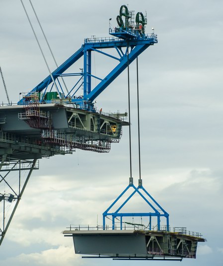
The cable supported composite box deck sections for the main bridge were pre-assembled at the site and transported by barge to their respective erection points. There are 109 sections in total ranging in length from 6.1m to 16.2m and weight from 260 tonnes to 780 tonnes. They were lifted approximately 50m from the delivery barge to permanent deck level. This was achieved using 6 no. temporary deck erection gantries using strand jack technology for lifting.
The unusual aspect was the need for the gantries to fit between the 2 planes of stay cables that are only 4m apart in the central section of the bridge. This led to a very slender structure that needed sophisticated control systems to limit eccentric loading from the lifting strand jacks and retractable feet to allow it to advance between lifting positions.
DLT developed and carried out detailed design of the gantries, including the lifting tackle, deck anchorages, deck segment adjustment and advancement M&E systems.
First deck unit lifted in September 2015.
Deck erection gantry manufacture model.
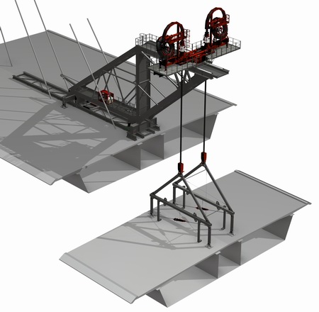
Detail of lifting strand jacks and plan alignment rams.
Detail of deck lifting frame with slope adjustment rams.


Launch of Approach Viaduct North (AVN)
There are 3 spans of 223m, 104m and 101.5m between the north tower (NT) and the north abutment (NA) passing over two piers N1 and N2. The transition between single cable stayed box girder and the twin box girders is located just to the north of the last pier N2. The last 222m of deck weighing 6400t including this transition was erected by launching from behind NA.
A king post and stay system was used to allow the deck to cantilever the full span length. The launch support bearings had to be changed during the launch to accommodate the transition in deck form. An unusual feature of the launch occurred towards the end when the nose was lifted to pass over the last pier by sliding the rear end down temporary ramp walls built in the north abutment
DLT developed and detailed the launch scheme, including permanent works interfaces and all temporary works, and provided site support during launching.
Deck Support Falsework at Piers S1 and S2
Erection of the deck segments over the southern approach piers S1 and S2 required extendable falsework to support and adjust the position of the pier deck segments to allow closure between them and the main cantilever deck. After the pier segment had been lifted onto the falsework, by the Erection Traveller, it was slid south over the pier to generate sufficient space to lift a further segment. Subsequently, the pier segment was moved north to connect it to the previously erected deck. The required longitudinal movement range was approximately 5m. There was also a requirement for hydraulic vertical supports to control the loading and in order to transfer the weight of the segment from the temporary supports onto the permanent bearings.
DLT developed the concept and carried out detailed design of the temporary works, permanent works interfaces and equipment specification.